
Understanding Calculations for Manual J, S, T and D
The Air Conditioning Contractors of America (ACCA) has developed standards and protocols for designing and installing HVAC equipment and duct work. Properly designed HVAC systems must go through the process of each of the four protocols — J, S, T and D.
A correct Manual Calculation leads to a well-designed HVAC system that improves overall performance, comfort and efficiency. Each manual plays a critical and unique role in the process.
What Is the Difference Between Manual J, S, T and D?
The HVAC system process includes:
- Manual J: Residential Load Calculation
- Manual S: Equipment Selection
- Manual T: Air Distribution Basics
- Manual D: Residential Duct Systems
ACCA Manual J is the first step and involves calculating the residential load. This stage impacts the remaining Manual processes. ACCA Manual S helps you select the right equipment for the job and relies on the calculation from using Manual J. ACCA Manual T involves sizing registers and grilles, and ACCA Manual D focuses on supply duct systems and registers.
Below, we’ll cover each manual in depth to further explore the differences, their uses and how to apply them.
Manual J: Residential Load Calculation
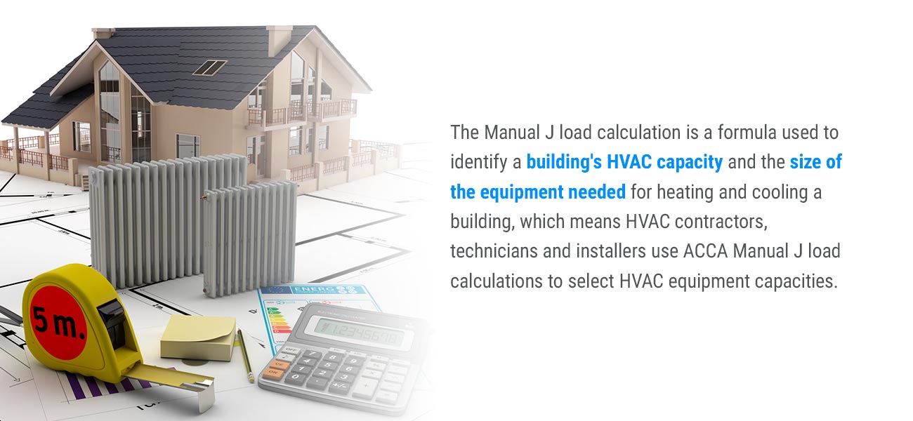
The first step of designing a residential HVAC system is following Manual J. The Manual J load calculation is a formula used to identify a building’s HVAC capacity and the size of the equipment needed for heating and cooling a building, which means HVAC contractors, technicians and installers use ACCA Manual J load calculations to select HVAC equipment capacities.
How Manual J Is Used
The Manual J calculation is used to determine what the correct size is for an HVAC unit without using excessive energy. Calculating the peak heating and cooling loads, or the heat loss and heat gain, is crucial for designing a residential HVAC system. HVAC contractors and designers use this calculation for every home and building they work on.
Manual J can be used to determine the heating and cooling needs for a specific home based on:
- The home’s location.
- The humidity of the climate.
- The direction the home faces.
- The insulation R-values of the walls, ceiling and floor.
The loads dictate both the equipment selection and the duct design used to deliver conditioned air throughout the house. As a result, Manual J impacts the processes of Manual S, Manual D and Manual T. When homeowners need to replace an existing furnace or A/C, they may simply select the same size as the latest model. However, if the original system wasn’t sized properly, the new system will also be improperly sized.
How to Do Manual J Load Calculations
To perform a Manual J HVAC calculation, follow these steps:
- Measure the building’s square footage: The first step is measuring the building’s square footage. You can measure the square footage of every room and add up the measurements of each individual room to get the total square footage. Omit areas of the building that don’t require heating and cooling, such as the basement or garage. This number may also be found on the blueprints of the building.
- Inspect the insulation: Assess the forms of insulation in the property, including the insulation in the walls, ceilings or floors. You may be able to discern this information from construction plans or blueprints. Additionally, consider external factors that impact the effectiveness of the insulation, such as airtightness, sun exposure and placement and size of windows.
- Determine how the interior space is used: Consider how the space in the building is used and how often it may need cooling or heating. Several factors play a role here, such as the number of people who use the space consistently and whether other appliances in the area produce heat, such as an oven. This can inform whether a building needs more or less HVAC power than expected.
- Identify the British Thermal Unit (BTU) of every element: The BTU measures the amount of heat that will raise an object’s temperature. This next step involves identifying the BTU values of the elements that indicate the HVAC needs of the building. BTU values may be assigned to variables used in the Manual J calculation, such as openings and people in a building.
- Calculate the total HVAC load: Finally, you can calculate the total HVAC load by inserting your measurements into the formulas to determine the total BTU and square footage. Add these solutions together to calculate the HVAC load. For example, you’d multiply the number of occupants by 100 BTU and the number of windows and exterior doors by 1,000 BTU, then add these numbers to the building’s square footage to get the total BTU.
After you complete this step, you can move on to Manual S.
Manual S: Equipment Selection
Manual S outlines specific procedures for choosing HVAC equipment based on design conditions and Manual J loads. Manual S utilizes original equipment manufacturer (OEM) data rather than the Air Conditioning, Heating and Refrigeration Institute certificate to size HVAC equipment. It specifies how small or large the capacity of the HVAC equipment can be when you compare it to the Manual J calculation.
When it comes to minimum rated efficiency value requirements like energy efficiency ratio, heating seasonal performance factor, seasonal energy efficiency ratio (SEER) and coefficient of performance, Manual S defers to the authority that has jurisdiction, such as LEED, Energy Star or a local permit office.
How Manual S Is Used
Manual S is a nationally-recognized standard that prevents issues associated with equipment due to being oversized or too small. Manual S is also a requirement under the International Residential Code. Manual S is used for the following purposes:
- Use the OEM data: With Manual S, you can interpret and apply the expanded performance data from the original equipment manufacturer.
- Identify sizing limits: Manual S sets sizing limits for equipment to ensure the capacity of the equipment will keep clients comfortable and prevent problems associated with the equipment being too large or too small. Issues that could arise from improperly sized equipment include lack of comfort, health issues due to excessive humidity, greater building costs, more wear and tear on the equipment and higher energy consumption.
- Select the right equipment: You can also use Manual S for instructions on how to select the equipment that meets your application requirements for latent cooling, sensible cooling and heating with the design conditions used for performing the load calculation.
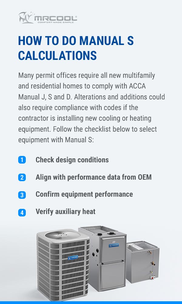
How to Do Manual S Calculations
Many permit offices require all new multifamily and residential homes to comply with ACCA Manual J, S and D. Alterations and additions could also require compliance with codes if the contractor is installing new cooling or heating equipment. Follow the checklist below to select equipment with Manual S:
- Check design conditions: Verify the design conditions are within the specifications and the information pulled from the Manual J load calculation has been accurately transferred.
- Align with performance data from OEM: Next, make sure the design parameters for calculating the heat load and the equipment manufacturer’s performance parameters match.
- Confirm equipment performance: See that the estimated cooling is based on the temperature difference and ensure the selected equipment satisfies the total BTUs for cooling the latent and sensible load. The selected equipment’s total heating capacity should be less than or equal to 140% of the total heating load designed. If this isn’t the case, the equipment size should be reduced. The total cooling capacity should be 115% of the total cooling load designed, and the equipment size should be reduced if it’s not.
- Verify auxiliary heat: Finally, confirm the heat pump balance point. Ensure the electric auxiliary heat provides the BTUs needed to make up for the difference between the capacity of the heat pump balance point and the design load conditions.
Manual T: Air Distribution Basics
Correctly sized registers and grilles are crucial for ensuring room comfort. Even if the right equipment is selected and the HVAC system and duct system are appropriately sized, the wrong registers and grilles could cause major problems in the system.
How Manual T Is Used
Drafts due to moving air in an HVAC system can lead to discomfort and stale air as a result of inadequate mixing. Even if there’s adequate conditioned air in a room, it can still feel uncomfortable if the air is sitting in one spot. Manual T offers air distribution requirements that lead to greater comfort in the home and better air mixing.
The following are some of the benefits of using Manual T:
- Prevent stagnant air.
- Avoid unwanted drafts.
- Improve the airflow in the building.
- Ensure air is properly mixed in every room.
- Place the supply and return registers properly.
How to Do Manual T Calculations
To accurately size HVAC grilles and registers, use the following steps:
- Review the direction of the jet, also known as the supply register throw and spread.
- Assess the pressure drop the registers and grilles produce.
- Confirm the return grille and supply register face velocities.
Manual D: Residential Duct Systems
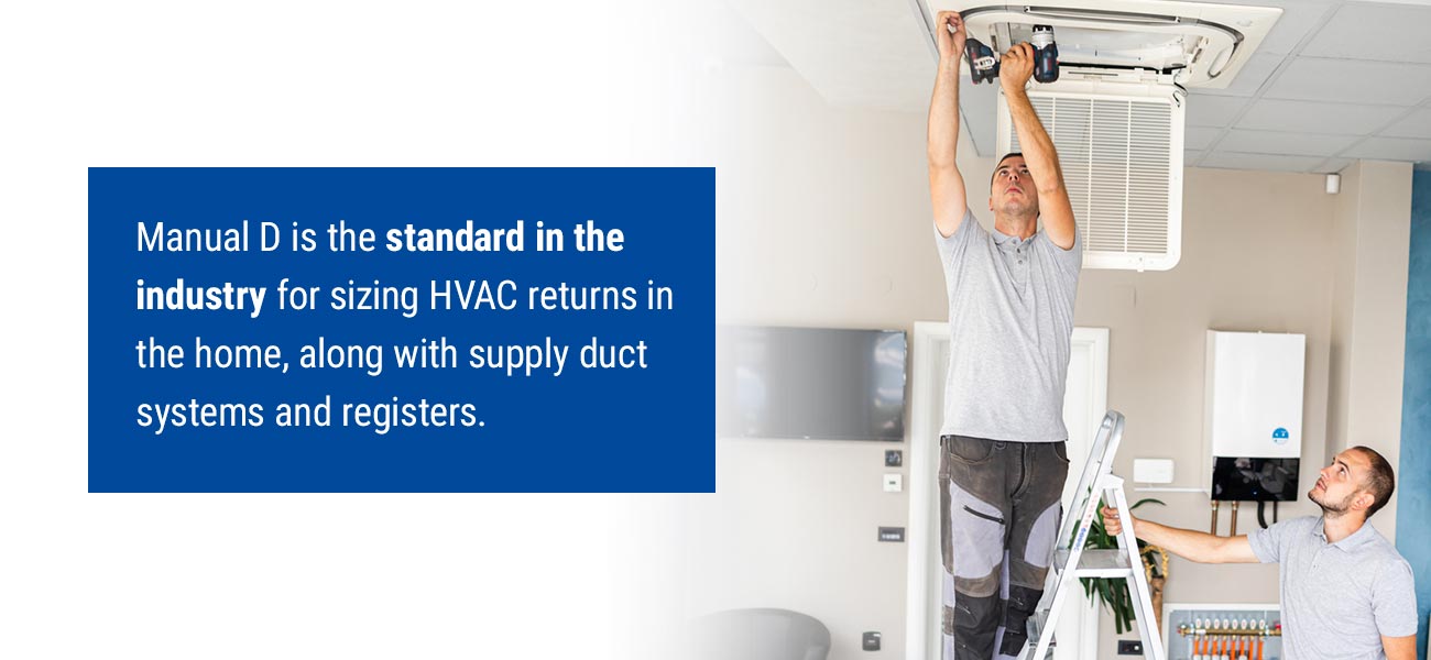
Manual D is the standard in the industry for sizing HVAC returns in the home, along with supply duct systems and registers. When a homeowner is ready to replace their old HVAC system or build their dream home, the residential Manual D duct design system is essential. Before HVAC equipment is purchased, this manual is followed to ensure optimal comfort in the home for years to come.
The A/C and furnace selected during the Manual S process determine the duct CFM that’s ideal for the humidity and summer and winter design temperatures. Similar to Manual J and Manual S, many permit offices require a Manual D duct design prior to issuing an HVAC permit, as this manual has a track record for being reliable.
How Manual D Is Used
Manual D is used to properly size HVAC supply and return ducts. Using the Manual J load calculation, Manual D distributes the proper amount of cooling and heating to every room. With the Manual D procedures, you can develop a duct blueprint you can use during installation, homeowners can review and code officials can inspect.
If HVAC ductwork is too large for a residence, rooms could become uncomfortable. If the ductwork is too small, the HVAC system could perform inefficiently and increase utility bills. A properly designed HVAC duct system should provide a residence with:
- Increased efficiency: As long as the duct design is performed adequately, a more affordable system could perform more efficiently than a high SEER system that has a poor duct design. With this improved efficiency, homeowners can enjoy lower heating and cooling costs, and the HVAC unit can run less frequently and for less time.
- Improved performance: Manual D should be used to design ductwork correctly and ensure the proper performance of cooling and heating equipment.
- Reduced wear and tear: A properly designed HVAC duct system may experience less wear and tear than a system that’s working harder as a result of duct design problems.
- Few equipment problems: A proper system can ensure adequate airflow. Without this adequate airflow, homeowners could face HVAC compressor problems, and the A/C coil may freeze up.
- Increased comfort in the home: The goal of a residential HVAC system is to ensure comfort in the home. A properly designed system achieves this and may even increase the value of the home.
- Reduced likelihood of mold development: If the air conditioning and heating ductwork are improperly sealed or leaky, this can quickly lead to moisture buildup and the development of mold.
- No uneven temperatures across rooms: A properly designed HVAC duct system can ensure temperature distribution is even across the home. An improperly designed system, on the other hand, could lead to rooms that are too cold during the winter and too hot during the summer.
How to Apply Manual D
To properly size ducts, an HVAC designer considers these components:
- Manual J load calculations to make sure the proper cooling and heating are supplied to every room.
- Properly sized return and supply main plenum according to the friction rate and velocity.
- Properly sized return grilles and supply registers according to Manual T air distribution.
- The layout of the home according to the floor plans.

Contact Us at MRCOOL for More Information
At MRCOOL, we make high-efficiency air conditioners and focus on innovation for the future. Our offerings include:
- Fans
- Window A/C units
- Central systems
- Water dispensers
- Ductless mini splits
- Packaged terminal air conditioners
When you choose MRCOOL, you get an excellent efficiency-to-cost ratio. We have the only true DIY system, and we supply high-quality conventional equipment. Explore our blog or contact us for more information about the calculations and applications for Manual J, S, T and D and about our products.
8 thoughts on “Understanding Calculations for Manual J, S, T and D”
Leave a Reply to Bob Burkholder Cancel reply


MR COOL
Master of All HVAC


I have a DIY-12 HP-WMAH-115C25
DYI-12-HP-C-115C-25
Question:
Does this unit have an overflow cut-off switch? City inspector requies one.
Got a red tag. He said we have to install one if there’s not one in there. Please give me guidance. Thanks. Stuart
The wall-mounted air handlers do not. A condensate pump can be added to the system.
Good afternoon, I have a client that purchased a system from you. Outdoor m# DIY-18-GP-WMAH-230B. He needs Manual-J & S calculations from me for permits. I can complete the Manual-J Calculations. What I am hoping you can help me with is the extended ratings for the product listed previously. I am not able to find them on your web site. We are in AZ, our design temperature is 105 degrees. Would you be able to provide me with documentation for this system’s capacity (sensible & latent)?
Thanks
You’ll be able to find documentation for all of our products at https://mrcool.com/documentation/! If what you need still isn’t available, please give us a call at 270-366-0457, or email us through our contact page at https://mrcool.com/contact/
Do you offer a dual fuel heat pump propane backup
Some of our retailers may offer similar configurations.
At what point in this process is the impact of humidity considered as a result of mechanical ventilation?
Humidity is considered in the Manual J process in order to select the correct size of HVAC system. In regards to specific mechanical ventilation, that would be a special circumstance that would also be considered during the Manual J process.